
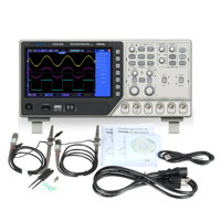
اوسلسكوب 2 جنل مختبري بتردد 100ميكا هرتز side image
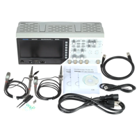
اوسلسكوب 2 جنل مختبري بتردد 100ميكا هرتز side image
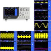
اوسلسكوب 2 جنل مختبري بتردد 100ميكا هرتز side image
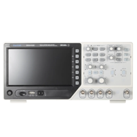
اوسلسكوب 2 جنل مختبري بتردد 100ميكا هرتز side image
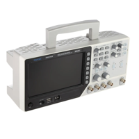
اوسلسكوب 2 جنل مختبري بتردد 100ميكا هرتز side image
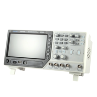
اوسلسكوب 2 جنل مختبري بتردد 100ميكا هرتز side image
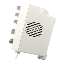
اوسلسكوب 2 جنل مختبري بتردد 100ميكا هرتز side image
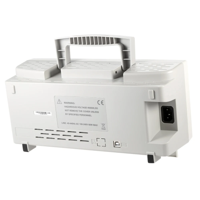
اوسلسكوب 2 جنل مختبري بتردد 100ميكا هرتز side image
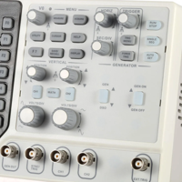
اوسلسكوب 2 جنل مختبري بتردد 100ميكا هرتز side image
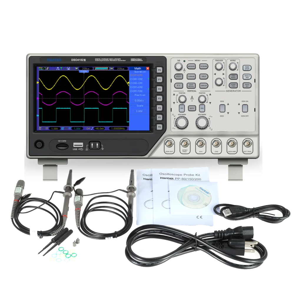
اوسلسكوب 2 جنل مختبري بتردد 100ميكا هرتز
IQD 715,000
الوصف
Model DSO4102S(DSO4102C)
Oscilloscope
Sample Rate Sampling Rate Range: 1GSa/s
Equivalent Sample Rate: 25GSa/s
Acquisition Modes
Normal Normal data only
Peak Detect High-frequency and randon glith capture
Average Wavefom Average, selectable 4,8,16,32,64,128
Inputs
Inputs Coupling AC, DC, GND
Inpits Impendance 1MΩ±2% ‖20pF±3pF
Probe Attenuation 1X, 10X
Supported Probe Attenuation Factor 1X, 10X, 100X, 1000X
Maximum Input Voltage CAT I and CAT II: 300VRMS (10×)
CAT III: 150VRMS(1×);
Installation Category II: derate at 20dB/decade above 100kHz to 13V peak AC at 3MHz* and above. For non-sinusoidal waveforms, peak value must be less than 450V. Excursion above 300V should be of less than 100ms duration. RMS signal level including all DC components removed through AC coupling must be limited to 300V. If these values are exceeded, damage to the oscilloscope may occur.
Horizontal
Sample Rate Range 1GS/s
Waveform Interpolation (sin x)/x
Record Length 40K
SEC/DIV Range 4ns/div to 40s/div
Sample Rate and ±50ppm(at over any ≥1ms time interval)
Delay Time Accuracy
Position Range 20ns/div to 80us/div; (-8div x s/div) to 40ms;
200us/div to 40s/div; (-8div x s/div) to 400s
Delta Time Measurement Accuracy
(Full Bandwidth) Single-shot, Normal mode:± (1 sample interval +100ppm × reading + 0.6ns);
>16 averages:± (1 sample interval + 100ppm × reading + 0.4ns);
Sample interval = s/div ÷ 200
Vertical
Vertical Resolution 8-bit resolution, all channel sampled simultaneously
Position Range 2mV/div to 10V/div
Bandwidth 100MHz
Rise Time at BNC( typical) 3.5ns
Analog Bandwidth in Normal and Average modes at BNC or with be, DC Coupled 2mV/div to 20mV/div, ±400mV; 50mV/div to 200mV/div, ±1V
500mV/div to 2V/div, ±40V; 5V/div, ±50V
Math +, -, *, /, FFT
FFT Windows: Hanning, Flatop, Rectamgular, Bartlett, Blackman;
1024 sample point
Bandwidth Limit 20MHz
Low Frequency Response (-3db) ≤10Hz at BNC
DC Gain Accuracy ±3% for Normal or Average acquisition mode, 5V/div to 10mV/div;
±4% for Normal or Average acquisition mode, 5mV/div to 2mV/div
DC Measurement Accuracy,
Average Acquisition Mode When vertical displacement is zero, and N ≥16:± (3% × reading + 0.1div + 1mV) only 10mV/div or greater is selected;
When vertical displacement is not zero, and N≥16: ± [3% × (reading + vertical position) + 1% of vertical position + 0.2div]; Add 2mV for settings from 2mV/div to 200mV/div; add 50mV for settings from 200mV/div to 5V/div
Volts Measurement Repeatability, Average Acquisition Mode Delta volts between any two averages of ≥16 waveforms acquired under same setup and ambient conditions
Trigger System
Trigger Types Edge, Video, Pulse, Slope, Over time, Alternative
Trigger Source CH1, CH2, EXT, EXT/5, AC Line
Trigger Modes Auto, Normal, Single
Coupling Type DC, AC, Noise Reject, HF Reject, LF Reject
Trigger Sensitivity
(Edge Trigger Type) DC(CH1,CH2):
1div from DC to 10MHz; 1.5div from 10MHz to 100MHz; 2div from 100MHz to Full;
DC(EXT):
200mV from DC to 100MHz; 350mV from 100MHz to 200MHz;
DC(EXT/5):
1V from DC to 100MHz;1.75V from 100MHz to 200MHz;
AC: Attenuates signals below 10Hz;
HF Reject: Attenuates signals above 80kHz;
LF Reject: Same as the DC-coupled limits for frequencies above 150kHz; attenuates signals below 150kHz
Trigger Level Range CH1/CH2: ±8 divisions from center of screen;
EXT: ±1.2V;
EXT/5:±6V
Trigger Level Accuracy( typical)Accuracy is for signals having rise and fall times ≥20ns CH1/CH2: 0.2div × volts/div within ±4 divisions from center of screen;
EXT: ± (6% of setting + 40mV);
EXT/5: ± (6% of setting + 200mV);
Set Level to 50%(typical) Operates with input signals ≥50Hz
Video Trigger
Video Trigger Type CH1, CH2: Peak-to-peak amplitude of 2 divisions;
EXT: 400mV;
EXT/5: 2V
Signal Formats and Field Rates, Video Trigger Type Supports NTSC, PAL and SECAM broadcast systems for any field or any line
Holdoff Range 100ns ~ 10s
Pulse Width Trigger
Pulse Width Trigger Mode Trigger when (< , >, = , or ≠); Positive pulse or Negative pulse
Pulse Width Trigger Point Equal: The oscilloscope triggers when the trailing edge of the pulse crosses the trigger level.
Not Equal: If the pulse is narrower than the specified width, the trigger point is the trailing edge. Otherwise, the oscilloscope triggers when a pulse continues longer than the time specified as the Pulse Width.
Less than: The trigger point is the trailing edge.
Greater than (also called overtime trigger): The oscilloscope triggers when a pulse continues longer than the time specified as the Pulse Width
Pulse Width Range 20ns ~ 10s
Slope Trigger
Slope Trigger Mode Trigger when (< , > , = , or ≠ ); Positive slope or Negative slope
Slope Trigger Point Equal: The oscilloscope triggers when the waveform slope is equal to the set slope.
Not Equal: The oscilloscope triggers when the waveform slope is not equal to the set slope.
Less than: The oscilloscope triggers when the waveform slope is less than the set slope.
Greater than: The oscilloscope triggers when the waveform slope is greater than the set slope.
Time Range 20ns ~ 10s
Overtime Trigger
Over Time Mode Rising edge or Falling edge
Time Range 20ns ~ 10s
Alternative Trigger
Trigger on CH1 Internal Trigger: Edge, Pulse Width, Video, Slope
Trigger on CH2 Internal Trigger: Edge, Pulse Width, Video, Slope
Trigger Frequency Counter
Readout Resolution 6 digits
Accuracy (typical) ±30ppm (including all frequency reference errors and ±1 count errors)
Frequency Range AC coupled, from 4Hz minimum to rated bandwidth
Signal Source Pulse Width or Edge Trigger modes: all available trigger sources
The Frequency Counter measures trigger source at all times, including when the oscilloscope acquisition pauses due to changes in the run status, or acquisition of a single shot event has completed.
Pulse Width Trigger mode: The oscilloscope counts pulses of significant magnitude inside the 1s measurement window that qualify as triggerable events, such as narrow pulses in a PWM pulse train if set to < mode and the width is set to a relatively small time.
Edge Trigger mode: The oscilloscope counts all edges of sufficient magnitude and correct polarity.
Video Trigger mode: The Frequency Counter does not work.
Measure
Cursor Measurement Voltage difference between cursors: △V
Time difference between cursors: △T
Recical of △T in Hertz (1/ΔT)
Auto Measuerment Frequency, Period, Mean, Pk-Pk, Cycli RMS, Minimum, Maximum, Rise time, Fall Time,
+Pulse Width, -Pulse Width, Delay1-2Rise, Delay1-2Fall, +Duty, -Duty, Vbase, Vtop, Vmid,
Vamp, Overshoot, Preshoot, Preiod Mean, Preiod RMS, FOVShoot, RPREShoot, BWIDTH,
FRF, FFR, LRR, LRF, LFR, LFF
Signal Source Mode
Waveform Impedance DC-25MHz
Sample Rate 200MHzDDS
Output Waveform Arbitrary wave/square wave/sine wave/triangle wave/trapezoidal wave/pulse wave/DC
Frequency Resolution 0.1%
Waveform Depth 2KSa
Vertical Resolution 12bit
Frequency Stability <30ppm
Waveform Range -3.5V~+3.5V
Output Impedance 50Ω
Output Current 50mA Ipeak=100mA
System BW 25M
Harmonic Distortion -50dBc(1KHz),-40dBc(10KHz)
General Features
Display
Display Type 7 inch 64K color TFT (diagonal liquid crystal)
Display Resolution 800 horizontal by 480 vertical pixels
Display Contrast Adjustable (16 gears) with the gress bar
Probe Compensator Output
Output Voltage( typical) About 5Vpp into ≥1MΩ load
Frequency(typical) 1kHz
Power Supply
Supply Voltage 100-120VACRMS(±10%), 45Hz to 440Hz, CATⅡ
120-240VACRMS(±10%), 45Hz to 66Hz, CATⅡ
Power Consumption <30W
Fuse 2A, T rating, 250V
Environmental
Temperature Operating: 32℉ to 122℉ (0℃ to 50℃);
Nonoperating: -40℉ to 159.8℉ (-40℃ to +71℃)
Cooling Method Convection
Humidity +104℉ or below (+40℃ or below): ≤90% relative humidity;
106℉ to 122℉ (+41℃ to 50℃): ≤60% relative humidity
Altitude Operating: Below 3,000m (10,000 feet);
Nonoperaring: Below 15,000m(50,000 feet)
Mechanical
Package Size Length 385mm, Width 200mm, Height 245mm
Weight 3.0KG(with Packing); 2.06KG(without Packing)
Material: ABS
Bandwidth: 100MHz
Plug Type: EU / US (Optional)
Power Supply: AC220V240V 50Hz / AC100120V 60Hz
Oscilloscope Probe Model: PP-150
Length of the Powerline: Apx. 150cm / 59.1in
Length of the USB Line: Apx. 107cm / 42.1in
Length of the Probe Line: Apx. 130cm / 51.2in
Size of the Oscilloscope Body: Apx. 31.5 12 15cm / 12.4 4.7 5.9in (L W H)
Oscilloscope Weight: 2.06kg/ 4.6lb
Package Size: Apx. 38.5 19.5 24cm / 15.1 7.7 9.4in
Package Weight: 2.97kg/ 6.6lb (2972.6g/104.8oz)
Package List:
1 * Digital Storage Oscilloscope
2 * Oscilloscope Probe
1 * Oscilloscope Powerline
1 * Hantek Data CD
1 * USB Line
1 * BNC to BNC Wire
التاكات
منتجات مشابه
مولد اشارة مختبري فنكشن جنيريتر من منفذين بتردد يصل الى 30 ميكا هرتز
IQD 175,000
محلل اشارة الدجتل ذو 16 منفذ و تردد 100 ميكا هرتز
IQD 125,000
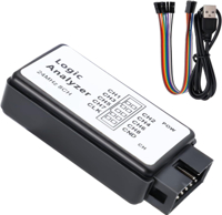
محلل اشارة الدجتل ذو 8 منافذ و تردد 24 ميكا هرتز
IQD 12,000
نظارات حماية شفافة
IQD 1,500
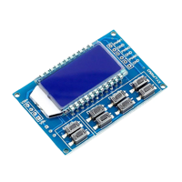
مولد اشارة نبضية من ثلاث مخارج بتردد مختلف من 1 هرتز الى 150 كيلو هرتز وفولتية عمل من 3 الى 30 فولت
IQD 5,000
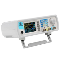
مولد اشارة مختبري فنكشن جنيريتر من منفذين بتردد يصل الى 15 ميكا هرتز
IQD 155,000
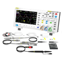
اوسلسكوب ثنائي من شركة فينرسي بتردد 100 ميكاهرتز وايضا يحتوي على مولد اشارة
IQD 240,000
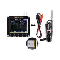
اصغر اوسلسكوب عملي من شركة فينرسي بتردد 200 كيلو هرتز
IQD 47,000
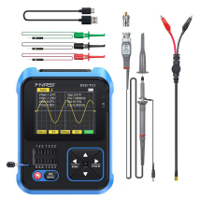
جهاز 3 في 1 من شركة فينرسي اوسلسكوب و فاحص ترانسسترا ومولد اشارة
IQD 85,000
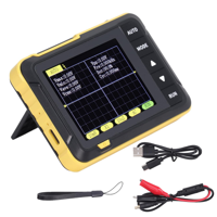
اوسلسكوب محمول صغير بجودة عالية وشكل عملي يعمل بتردد 200 كيلو هرتز من شركة فرنسي
IQD 39,750
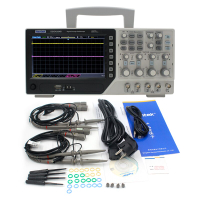
اوسلسكوب مختبري 4 جنل من شركة هانتك يعمل بتردد 200 ميكا هرتز
IQD 935,000
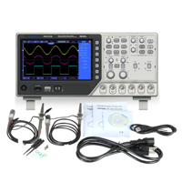
اوسلسكوب 2 جنل مختبري بتردد 100ميكا هرتز
IQD 715,000
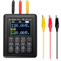
مولد ومنظم اشارة من 0 الى 10 فولت و 4 الى 20ملي امبير للتطبيقات الصناعية وفحس الحساسات الصناعية
IQD 101,000
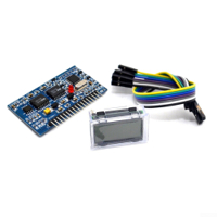
مولد اشارة جيبية مع شاشة LCD
IQD 19,500
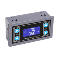
مولد اشارة PWM
IQD 9,500
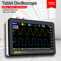
اوسلسكوب محمول 2 جنل 100 ميكا هرتز مع شاشة لمس ملونة
IQD 260,000
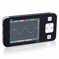
اوسلسكوب جيبي
IQD 158,000
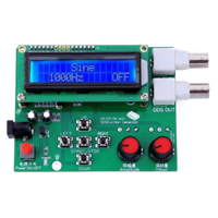
مولد اشارات جيبة ومربعة ومثلثة بترددات مختلفة من 1 هرتز الى 65 كيلو هرتز
IQD 25,000
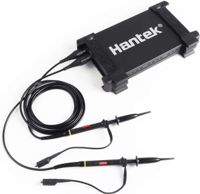
اوسلسكوب 2 جنل يربط على الحاسوب
IQD 139,000
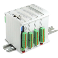
متحكم صناعي plc 58 مدخل ومخرج
IQD 625,000
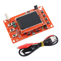
اوسلسكوب محمول DSO138
IQD 30,000
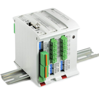
جهاز PLC اردوينو 38 مدخل ومخرج
IQD 650,000
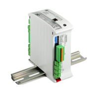
اردوينو plc اردوبوكس انالوك
IQD 414,000
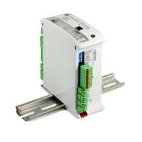
اردوينو plc اردوبوكس ريلي
IQD 430,500
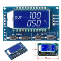
مولد اشارة pwm بتردد من 1الى 150 كيلو هرتز مع شاشة
IQD 2,500
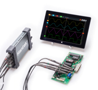
أوسلسكوب محمول دجتل مع الحاسوب
IQD 480,000
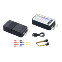
محلل اشارة رقمية 8 قنوات من شركة سبيد
IQD 31,000
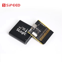
محلل اشارة رقمية مكون من 16 منفذ مع يو اس بي 3 من شركة سبييد
IQD 155,000

IQD 7,000

مولد اشارة متذبذبة مربعة بتردد مختلف مع شاشة ومتحكم دوار
IQD 6,000